Control water-based or electric underfloor heating, with a thermostat that works without the app.
Updated August 2026
Water-based underfloor heating
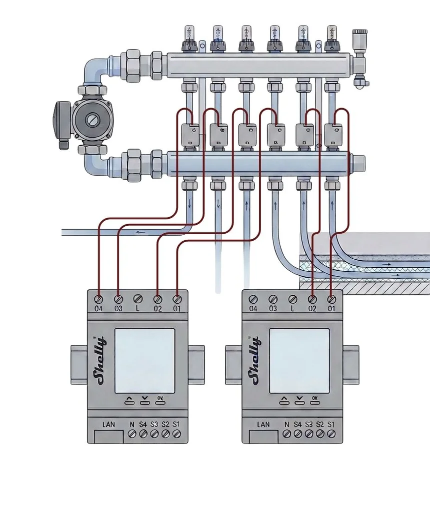
The loops terminate at a manifold, and each is opened and closed by a thermal actuator. Count the actuators, not the rooms: a manifold with six loops needs six switched outputs.
1
Hardware
Choose the relay
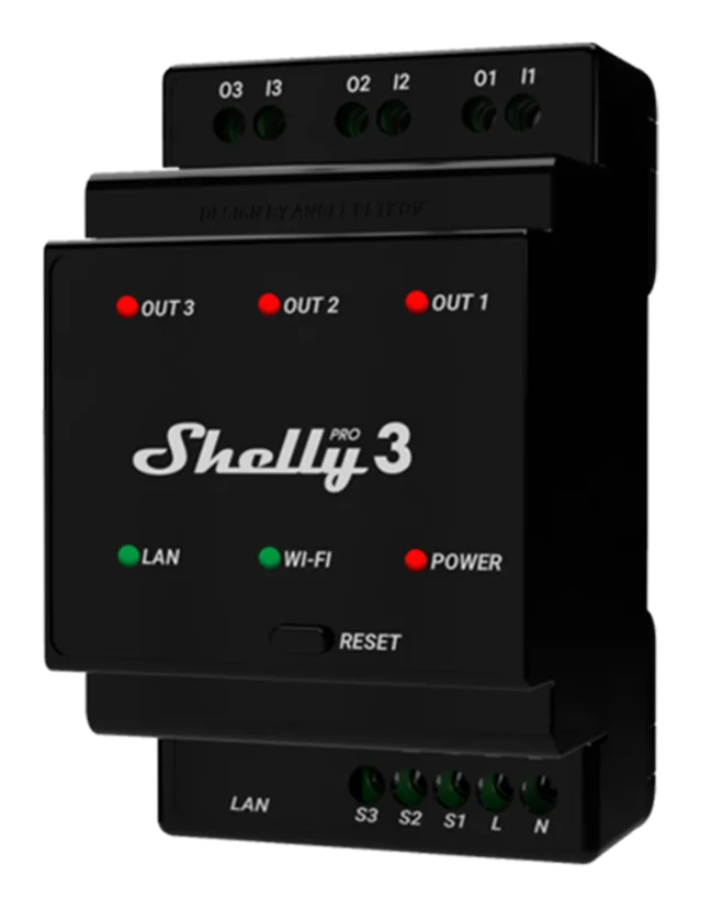
Shelly Pro 3 gives three potential-free dry contacts. Use it for 24 V actuators, or where the manifold already has its own supply.
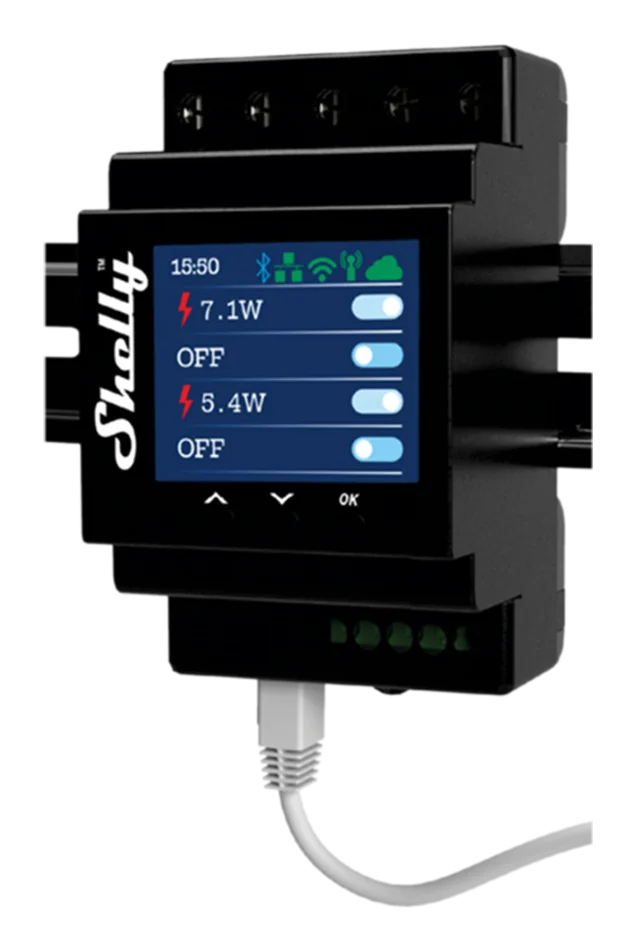
Shelly Pro 4 PM gives four channels with built-in 230 V switching and per-channel power metering. Use it when the customer wants consumption per zone.
Both mount on DIN rail, so they sit in the cabinet beside the manifold.
2
Sensor
Choose the temperature sensor
Water-based systems are slow, so room temperature is normally the control variable and the floor probe is a limit rather than the target.
Mains-powered probe, battery room sensor, or the Wall Display's own sensor.
Mains-powered: a Plus, Gen3 or Gen4 relay with the Shelly Plus Add-On and a DS18B20 probe — the choice when a probe is embedded in the screed.
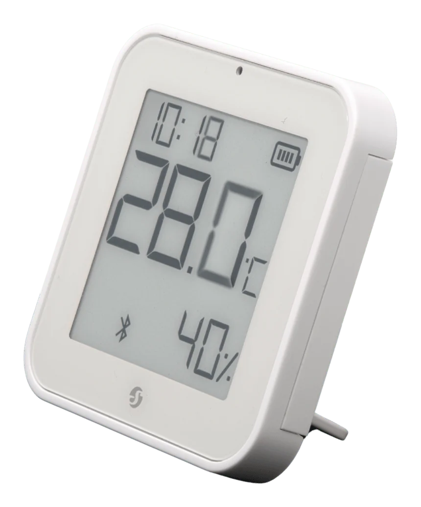
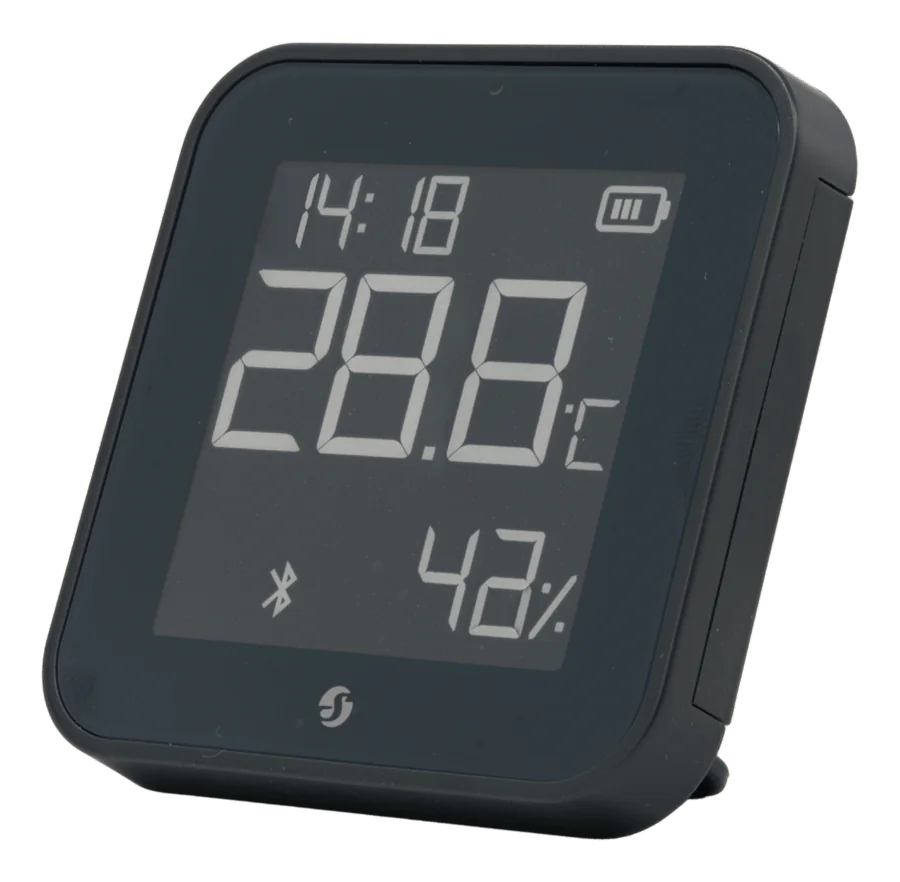
Battery-powered:Shelly BLU H&T ZB or H&T Gen3 for room temperature. Mount at 1.5 m, away from radiators, direct sun and external walls.
3
Wiring
Wire the manifold
Connect each actuator to its own relay output, and bring the circulation pump under the same controller so it only runs when at least one loop is open.
L
Line — common feed for 230 V actuators
N
Neutral — use the manifold's neutral bar for the actuator return
O1–O4
Actuator outputs, one per zone
S1–S4
Optional inputs, e.g. existing room thermostats kept as a manual override
The pump is interlocked so it only runs when a zone calls for heat.
Torque every terminal to the value printed on the device before re-energising.
4
App setting
Set up the thermostat
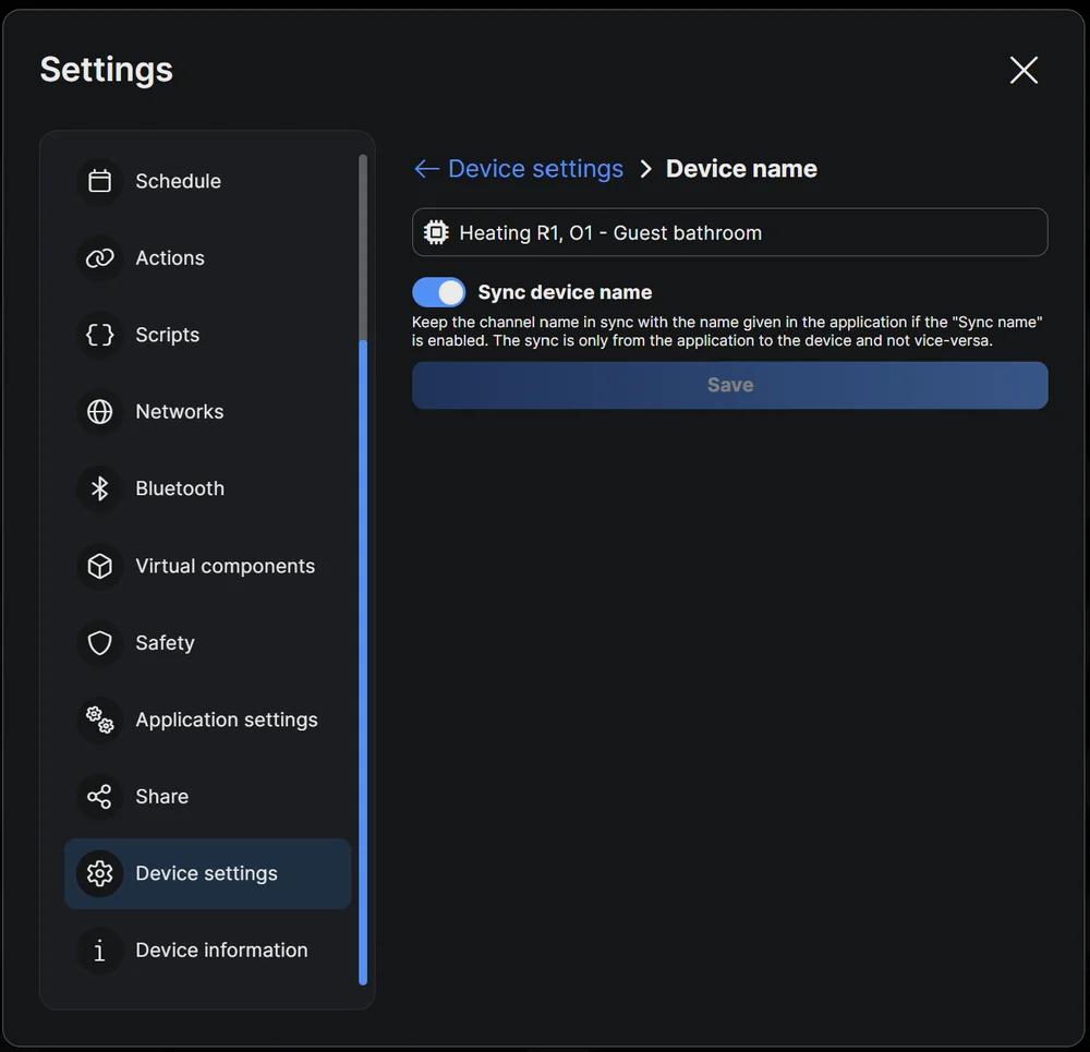
Rename each output after the room it feeds before you do anything else — “O2” means nothing to the customer, “Bathroom” does.
In Shelly Smart Control, go to Home → Add new → Thermostat, select the output that switches the heat, select the temperature sensor, then set the target and build a weekly schedule. The same setup is available at control.shelly.cloud.
Any Shelly relay plus any Shelly temperature sensor becomes a thermostat this way. It is not specific to underfloor heating — the same pairing drives an electric radiator, a convector, a towel rail, or an air conditioner in cooling mode, where the output switches on above the target instead of below it.
The mode tells the device what to expect from the load.
Hysteresis — the setting that decides whether it behaves
The gap between switching off and switching on again. Target 21 °C with 0.5 °C of hysteresis means the heat runs until 21.25 °C and returns at 20.75 °C.
Too tight and the relay chatters. A slow load cannot respond inside a narrow band, so the output cycles without the room temperature changing.
Too wide and the room swings — two degrees reads as cold-then-warm rather than steady.
Load
Start at
Electric underfloor heating
0.5 °C
Water-based underfloor heating
1.0 °C
Electric radiator or convector
0.3–0.5 °C
Air conditioning in cooling mode
0.5–1.0 °C
Start there and tighten only if the room actually overshoots. The instinct to set it tight for accuracy makes slow systems worse.
If a room never reaches its target
Check the sensor offset before anything else. A sensor behind a curtain or above a radiator reads several degrees off, and the offset corrects it without moving the sensor.
Use the offset when a sensor reads consistently high or low.
5
Test
Commission and hand over
Call each zone individually and confirm the right actuator opens — six identical white actuators look the same in February. Compare measured power against the rated output of the actuator group; a large gap usually means a wiring fault or a dead actuator, not a faulty meter.
Label the outputs before you close the cabinet, and check Wi-Fi signal strength before the lid goes on.
Electric underfloor heating
A heating mat or cable is cast into the floor of a single room — typically a bathroom or kitchen — and there is usually an existing thermostat position with a back-box on the wall.
Shelly 1PM Gen4 switches up to 16 A / 3,680 W, fits a standard back-box and reports real power. One device per room keeps the wiring short and lets every room run its own schedule.
Check the mat rating first: a 10 m² mat at 150 W/m² draws about 6.5 A, well inside the relay, but a large open-plan floor can exceed 16 A and needs splitting across two circuits.
The relay switches the element; the Add-On reads the floor probe.
Fit a floor probe, not just a room sensor
Electric heating warms the surface directly, so surface temperature is the variable that matters. Without a floor probe you risk cooking sensitive flooring, and a room sensor alone cannot promise a warm floor on a cold morning.
Run the probe in a sensor tube with a plugged end so it can be replaced without breaking up the floor, and keep it midway between two heating loops — never on top of one.
L
Line in, 110–240 V AC
N
Neutral
O
Output to the heating element
SW
Optional manual switch input
VCC
DS18B20 red — 3.3 V supply
DATA
DS18B20 yellow — 1-Wire data
GND
DS18B20 black — ground
Create the thermostat as above, using the floor probe as the temperature source, then set a hard upper limit. Cap wood floors at 27 °C to protect parquet and engineered board — and check the flooring manufacturer’s figure, since some are lower. Start hysteresis around 0.5 °C for electric heating.
Use the offset to correct a probe reading that sits consistently high or low.
Wall Display as a standalone controller
When the customer wants a physical thermostat on the wall that keeps working without the app, the cloud or the internet.
Pair a Shelly BLU H&T ZB straight to the display over Bluetooth — Settings → Bluetooth devices → Add, then put the sensor into pairing mode. From the home screen choose the Floor heating tile, assign the sensor as the temperature source and the relay output as the actuator, then set the target and schedule on the device itself.
Introduction
Shelly controls both water-based and electric underfloor heating. The logic runs either in the thermostat function of Shelly Smart Control, or in the floor-heating controller built into the Wall Display.
The hardware choice comes down to one question: is the heat controlled centrally at a manifold, or per room behind a thermostat? Water-based systems terminate at a manifold, so one DIN-rail relay covers several zones. Electric mats are cast into a single room’s floor and need one relay each.
Tips & best practices
Night setback pays for itself. Dropping 2–3 °C overnight cuts consumption without losing morning comfort — as long as recovery starts early enough for a slow floor.
Tie heating to the spot price. Pre-heat in cheap hours and coast through the expensive ones. See live electricity prices.
Use both sensors where you can. Floor probe as the safety limit, room sensor as the comfort target.
Keep the existing wall thermostat if you want — wire it into SW as a manual override, or leave it set to maximum. Do not put both in series and expect predictable behaviour.
Schedules survive a network outage. The thermostat logic runs on the device, so heating continues on the last known schedule. You lose remote control, not the heat.
Video tutorial
Setting up a heating control from scratch, including sensor pairing and the schedule. It covers the thermostat function generally, not only underfloor heating.