1. Home
  2. Installations
  3. Access control

Installations

Access control with Shelly

Add remote unlock and notifications to an existing lock, without replacing it.

Updated August 2026

What this covers

A Shelly relay turns an existing 12 V or 24 V electronic lock into one you can open from the app, on a schedule, or from a keypad — without replacing the lock itself.

Three common jobs, all the same wiring:

  • Remote unlock only. A Shelly 1 Gen4 and a three-second Auto-Off Timer. No keypad.
  • Keypad or fingerprint scanner. The reader’s output wires into the Shelly’s SW input, so any 12 V/24 V third-party reader works.
  • Scheduled access. The relay is disabled outside opening hours, so codes are simply ignored.

Lock types

Most 12 V and 24 V electronic locks work with Shelly. Which one is fitted decides what happens in a power cut, and that is the decision that matters.

Magnetic lock — fail-safe

Powered on to stay locked, releases the moment power is cut. The door opens if power fails. Holding force is typically 150–500 kg.

Common on emergency exits and glass doors.

Electric strike — fail-secure

Powered briefly to release the latch, mechanically engaged otherwise. The door stays locked if power fails. Available in AC and DC variants.

Common on office doors and residential gates.

Electromechanical lock — configurable

Motor-driven, with several states, and it can be set up either way. Often reports its own status. Draws considerably more current during a cycle.

Common in high-security and commercial installations.

What you need

Component Recommended Notes
Relay Shelly 1 Gen4 12 V DC, 24–48 V DC or 110–240 V AC, potential-free output
Lock Any 12 V or 24 V electronic lock Powered separately from the relay
Keypad or scanner Any third-party 12 V/24 V reader Output wires to the Shelly’s SW input
Door sensor, optional Reed switch and Shelly Plus Add-On Real open/closed state rather than “a pulse was sent”

The 1 Gen4’s universal supply is what makes this work across almost any lock system — the same device suits a 12 V strike and a 24 V maglock.

Installation

Five steps. Read the safety notice before starting.

1
Planning

Confirm four things first

  • The lock’s voltage and current draw
  • Whether it is fail-safe or fail-secure — it changes the wiring logic
  • Whether a keypad or scanner is coming now or later
  • That a mechanical key backup is in place

The last one is not a formality. If there is no key cylinder, that is the first thing to fix, before any of this.
2
Wiring

Wire the relay

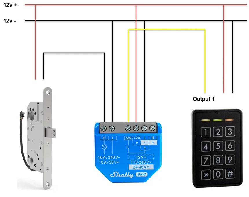
The relay’s potential-free output controls power to the lock. The reader’s own relay output goes to the SW input — so a valid code triggers the Shelly exactly as a manual switch press would.

L
Supply, 12 V DC / 24–48 V DC / 110–240 V AC
N
Supply return
O
Potential-free output — to the lock
I
Potential-free common — to the lock
SW
Input — from the keypad or scanner output
Wiring diagram showing a Shelly 1 Gen4 controlling a 12 V electronic lock with a keypad output wired to the SW input
The lock is powered separately; the relay only switches it. The reader triggers the SW input.
3
App setting

Set the Auto-Off Timer

Without it the door stays unlocked after every access. With it, the lock releases and re-engages by itself.

Timer settings → enable Auto-Off → 3 seconds

4
Wiring

Connect the keypad or scanner

Most readers include a relay output meant to drive a lock directly. Wire that output to the SW input instead of to the lock, and the Shelly does the switching.

Skip this step on an app-only installation.

If the reader will not trigger the Shelly, it is usually because it provides a dry contact rather than a voltage signal. Check the reader’s documentation and set the input type accordingly.

5
Test

Test the whole chain

Four tests, and the last one is the one people skip:

  • From the reader — a valid code releases the lock for three seconds, then it re-locks
  • From the app — same behaviour
  • From a schedule, if configured — a code outside the window is ignored
  • The mechanical key — still works

Add schedules and notifications afterwards if the customer wants them: a schedule that disables the relay outside opening hours, and an action that notifies on unlock. For real door state rather than “a pulse was sent”, add a reed switch on the Plus Add-On.

Tips & best practices

  • The mechanical backup is not optional. Electronic access must never be the only way in or out.
  • Lock buzzing or humming? Check whether it is an AC or DC type. Some 12 V locks need AC to hold quietly.
  • Fail-safe locks open in a power cut. If continuous locking matters, plan a UPS — and tell the customer what happens without one.
  • Fail-secure locks stay locked in a power cut. Always pair with a mechanical override on the inside.
  • Add a reed switch. Knowing the door is actually closed catches both a forced entry and a door left ajar, which a relay alone never will.